

 español
 English
 français
 Deutsch
 العربية
 中文
中文
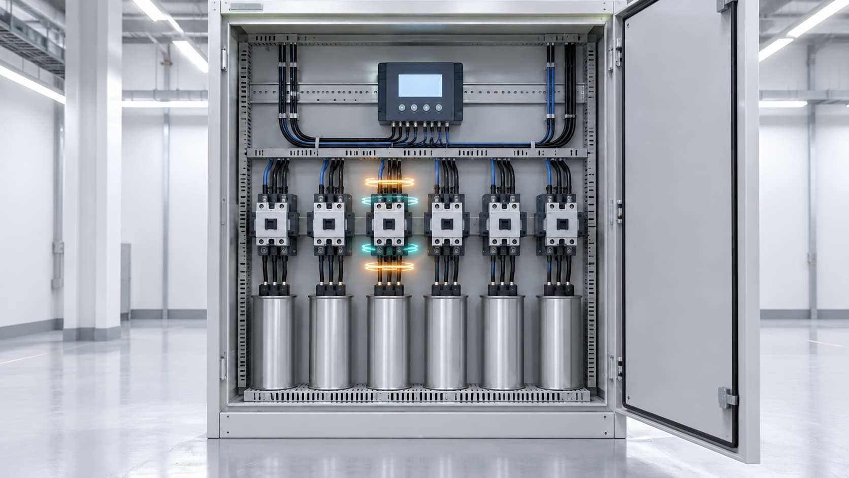
An automatic power factor correction (APFC) panel should switch capacitor stages as reactive-power demand changes. Occasional switching is normal. However, when the same stages connect and disconnect repeatedly without a meaningful load change, the panel may be experiencing capacitor step hunting.
Hunting is more than an irritating clicking sound. Excessive operation can wear contactors, stress capacitors, create voltage changes, and shorten panel life. It may also prevent the system from maintaining a stable power factor.
Finding the cause requires reviewing the steps, load, controller settings, CT installation, and component condition together.
An APFC controller measures power factor or reactive power and compares it with a target. It connects capacitor stages when the system needs capacitive reactive power and disconnects them when compensation becomes excessive.
Hunting occurs when this process cannot reach a stable operating point. For example, the system may be slightly inductive before a 25 kVAr stage connects but become too capacitive afterward. The controller removes the stage, making the system inductive again. The cycle then repeats.
Not every repeated operation is hunting. Rapidly changing loads may genuinely require frequent compensation, so compare switching records with the load cycle.
If the required correction is smaller than the minimum stage, connecting that stage causes overcompensation, while removing it causes undercompensation. This often appears during night, weekend, or seasonal light-load periods when a panel designed for maximum demand cannot make a sufficiently small adjustment.
Welders, presses, hoists, and similar equipment can change reactive demand faster than a contactor-switched bank can follow. The load may change again before a delayed command occurs.
A longer control delay may ignore brief fluctuations, but too much delay can leave sustained demand uncorrected. Highly dynamic loads may need thyristor-switched stages or continuously variable compensation such as an SVG, following an engineering review.
A target extremely close to unity leaves little room for load movement and measurement variation. The controller may repeatedly exchange stages while chasing a value that the available step sizes cannot hold.
The target should meet site and utility requirements without producing a leading power factor.
Sensitivity or C/k determines when switching is triggered. If it does not match the first stage and CT ratio, the controller may switch too easily or select stages poorly.
Switching delay and capacitor discharge delay also serve different purposes. The first prevents reactions to short changes; the second prevents premature re-energization. Both must follow the controller and capacitor-bank manufacturer’s instructions.
Incorrect CT location, polarity, ratio, phase relationship, or wiring can mislead the controller. The CT must measure both the load and capacitor-bank response as intended.
At low current, check measured kW and kVAr rather than relying only on displayed power factor.
A blown fuse, failed contactor pole, loose connection, or degraded capacitor can reduce a stage’s kVAr. The controller may add stages because the expected correction never appears.
A welded contactor creates the opposite problem: a capacitor remains connected even when the controller shows it as off. The other stages may then cycle while the controller tries to correct a condition outside its control.
Two APFC panels can hunt if they measure overlapping loads. One connects a stage, causing the other to remove one. Fixed capacitors can create a similar conflict. Coordination may require revised CT locations, delays, or targets.
| Observed behavior | Possible cause | First check |
|---|---|---|
| Smallest stage repeatedly switches | Stage too large or sensitivity unsuitable | Actual kVAr demand and C/k setting |
| Switching increases at light load | Overcompensation | Leading kVAr and fixed capacitors |
| Stages react to short load pulses | Control delay too short | Load trend and switching interval |
| Stage display and measured current disagree | Fuse, contactor, or capacitor fault | Current in each stage |
| Two banks alternate their switching | Controllers are interacting | CT locations, targets, and delays |
| Power factor moves the wrong way | CT polarity or phase error | Wiring and manual stage test |
Use these patterns to guide testing, but confirm the cause with measurements.
Record power factor, kW, kVAr, current, voltage, and stage status over a representative cycle. Conditions before and after each command are more useful than a single reading.
Test every stage using the manufacturer’s procedure. Confirm the expected current, direction of reactive-power change, contactor release, and reconnection delay. Safely isolate the panel before inspecting fuses, connections, capacitors, ventilation, and contactors.
Compare the controller configuration with the installed system. Verify CT ratio and polarity, voltage measurement phase, target power factor, stage ratings, switching sequence, sensitivity or C/k, and applicable delays. Never shorten the required capacitor discharge time simply to obtain a faster response.
If the minimum stage remains too large, consider a smaller stage, different step ratio, coordinated fixed and automatic compensation, or variable compensation for dynamic loads.
Review harmonic measurements before changing capacitor capacity because doing so can alter resonance conditions. Select detuned banks, SVGs, or hybrid solutions from actual power-quality data rather than switching frequency alone.
Every contactor operation causes wear, while capacitor energization produces inrush current. Excessive cycles can damage contacts and fuses. Switching counters can reveal abnormal cycling and uneven wear.
There is no universal interval. It depends on the load, controller, switching method, and component ratings. Reversal of the same stage without a meaningful load change should be investigated.
It may help when brief load fluctuations cause unnecessary commands. It cannot correct oversized stages, CT errors, failed components, or controllers working against each other.
Not necessarily. The controller may be responding correctly to unsuitable step sizes, unstable loads, wrong settings, or inaccurate measurements. Check the complete control loop before replacing it.
An SVG provides variable electronic compensation without mechanically switched capacitor stages. It can suit fast-changing loads, but rating, harmonics, system conditions, and cost still require review.
An APFC panel usually hunts because it cannot find a stable balance between reactive-power demand and the compensation available. Possible causes include an oversized minimum stage, changing loads, aggressive targets, incorrect settings, CT errors, failed equipment, or interacting banks.
Measure the sequence, verify every stage, and review the complete control arrangement before changing parameters. The objective is not simply fewer clicks, but stable power factor and reliable component operation.
YT Electric can review your load profile, APFC settings, capacitor stages, and power-quality measurements to identify the cause of hunting and recommend an appropriate correction strategy.



 compatible con la red ipv6