

 español
 English
 français
 Deutsch
 العربية
 中文
中文
Filtro armónico activo: prolonga la vida útil del transformador.
Un transformador de 480 V que funciona dentro de su potencia nominal (kVA) puede experimentar un aumento de temperatura anormal cuando los variadores de frecuencia, los rectificadores de los sistemas de alimentación ininterrumpida (UPS) y las cargas conmutadas inyectan corriente armónica elevada en su bus secundario. El transformador no solo recibe la corriente fundamental útil, sino que también transporta corriente distorsionada a través de sus devanados, terminaciones y conductor neutro durante horas.
UnFiltro armónico activoMide la forma de onda de la corriente de carga e inyecta una corriente de compensación con contenido armónico opuesto. Utilizado junto con una revisión térmica adecuada del transformador, reduce el componente armónico que provoca pérdidas adicionales por efecto Joule, pérdidas parásitas y calentamiento localizado. No aumenta la potencia nominal del transformador; simplemente elimina un mecanismo de carga que consume margen térmico.
El calentamiento del transformador comienza con la corriente. La corriente de carga fundamental genera las pérdidas esperadas en el bobinado, pero la corriente armónica aumenta la corriente RMS y modifica la forma en que las pérdidas se distribuyen a través de los conductores y las partes estructurales.
Las pérdidas de cobre siguen la relación $I^2R$, por lo que una corriente RMS más alta genera calor de forma desproporcionada. Las corrientes armónicas de alta frecuencia también aumentan las pérdidas por corrientes parásitas y dispersas; el resultado depende de la construcción del transformador, el espectro y la temperatura, no solo de THDi.
Los armónicos triples (el tercero, el noveno y el decimoquinto) son componentes de secuencia cero en sistemas trifásicos de cuatro hilos. Se suman al neutro en lugar de cancelarse, por lo que las cargas monofásicas no lineales pueden sobrecalentar las terminaciones del neutro incluso cuando la carga de fase parece aceptable.
Las altas temperaturas repetidas aceleran el envejecimiento del aislamiento y los ciclos térmicos pueden aflojar las conexiones. Un estudio armónico debe relacionar los datos de la forma de onda con el riesgo de puntos calientes, y no tratar el THDi únicamente como un valor de cumplimiento.
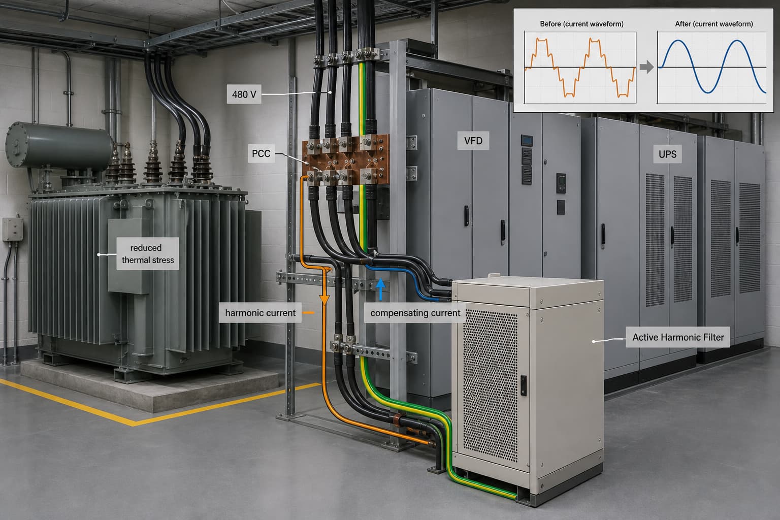
ATransformador industrial de 480 V que alimenta cargas de variadores de frecuencia y sistemas de alimentación ininterrumpida (UPS), con un filtro activo de armónicos conectado en paralelo en el punto de conexión común (PCC).
Un AHF es una fuente de corriente conectada en paralelo, no un dispositivo de impedancia en serie. Los transformadores de corriente muestrean la corriente de carga o de alimentación; el controlador separa los armónicos seleccionados y ordena al inversor que inyecte una corriente de compensación igual y opuesta. En consecuencia, el transformador aguas arriba suministra una forma de onda de corriente más cercana a la componente fundamental.
La modulación SPWM determina la precisión con la que el inversor sigue la corriente de referencia. Un muestreo rápido y una sintonización estable del bucle de corriente son cruciales durante los cambios de carga del variador de frecuencia; al seleccionarlo, se deben verificar los órdenes armónicos, la ubicación del transformador de corriente, la secuencia de fases y la prioridad de las funciones cuando la capacidad es limitada.
Una topología de 3 niveles aplica incrementos de voltaje menores que un inversor de 2 niveles comparable, lo que reduce la tensión dv/dt en los dispositivos de conmutación y los componentes del filtro. Verifique la frecuencia de conmutación, la temperatura de la unión del semiconductor, la ventilación y la reducción de potencia de salida en las condiciones ambientales reales del sitio.
A 45 °C, la temperatura del aire del gabinete, el polvo y la separación entre paneles pueden determinar la producción continua. Solicite al fabricante la potencia nominal a plena carga a esa temperatura ambiente; las pérdidas por conmutación de los IGBT o MOSFET de SiC, las pérdidas magnéticas y el rendimiento del ventilador influyen en el aumento de la temperatura interna.
|
Criterio |
Filtro pasivo |
Filtro armónico activo |
|
Principio de funcionamiento |
Utiliza ramas LC sintonizadas para desviar las frecuencias armónicas objetivo. |
Inyecta una corriente de compensación medida en paralelo con la carga. |
|
Espectro armónico |
Eficaz para pedidos diseñados; el rendimiento puede variar con la impedancia de la red. |
Puede dirigir múltiples órdenes programadas dentro de su ancho de banda nominal actual. |
|
Respuesta a cambios en la carga del variador de frecuencia/UPS |
Ajuste fijo; puede desajustarse a medida que cambia el perfil de carga. |
El controlador sigue los cambios en la corriente de carga dentro de sus límites de respuesta y capacidad. |
|
Consideración de resonancia |
Requiere una revisión detallada del condensador y la resonancia del sistema. |
No elimina los requisitos de estudio de la red, pero evita las ramas de condensadores sintonizados como mecanismo principal. |
|
Función de potencia reactiva |
Puede suministrar potencia reactiva fija como parte del diseño del filtro. |
Puede asignar la corriente disponible a la compensación dinámica de potencia reactiva si está configurada. |
|
Relevancia de la vida de los transformadores |
Puede reducir la corriente armónica seleccionada cuando está sintonizado correctamente. |
Reduce la corriente armónica medida y puede incluir compensación de corriente neutra para sistemas de cuatro hilos. |
La capacidad del AHF se especifica en amperios porque la unidad inyecta corriente de compensación real. Registre la corriente de fase, el espectro, el ciclo de trabajo, la corriente neutra, la tensión, el nivel de falla y las futuras adiciones de carga; califique el filtro para la corriente armónica más el crecimiento definido y el margen de reducción de temperatura.
THDi se refiere a la corriente fundamental, por lo que porcentajes idénticos pueden representar demandas de corriente armónica muy diferentes. Un bus con poca carga puede tener un THDi alto pero una demanda moderada, mientras que un bus con mucha carga y un THDi menor puede requerir un filtro de mayor tamaño. Utilice la corriente armónica junto con los datos térmicos del transformador.
Defina la demanda armónica antes de reservar capacidad AHF para corriente reactiva. Utilice SVG donde la compensación dinámica de potencia reactiva sea dominante; considere STATCOM para la estabilización de tensión de media tensión más allá del alcance de AHF de baja tensión.
|
Estado del sitio |
Medición o entrada de diseño |
Lógica de selección AHF |
Enfoque en la instalación y el mantenimiento |
|
480 V Línea de producción con alta concentración de variadores de frecuencia |
Corriente armónica por orden, pasos de carga, tendencia de puntos calientes del transformador |
Tamaño para la corriente armónica dominante medida más margen de crecimiento definido; verificar seguimiento rápido |
Dirección de la CT, ventilación del panel, capacidad de corriente del cable, inspección periódica de la conexión |
|
Carga de oficina o de datos trifásica de cuatro hilos |
Corriente de fase, corriente neutra, espectro triple |
Seleccione un AHF de cuatro hilos con compensación de corriente neutra dimensionado a partir de la corriente de secuencia cero medida. |
Estudio de temperatura del conductor neutro y de la terminación; coordinación de UPS |
|
Instalación de banco de condensadores existente con fallos repetidos |
Espectro de voltaje, eventos de conmutación de condensadores, impedancia de red |
Realice una revisión completa de la resonancia antes de integrar AHF; no asuma que AHF corrige un esquema de condensador dañado. |
Evaluar el aislamiento del banco de condensadores, los ajustes de protección y el punto de medición del PCC. |
|
Sala eléctrica industrial polvorienta a 45 °C |
Máximo de horas de funcionamiento a plena carga en condiciones ambientales y de polvo. |
Aplique la reducción de temperatura confirmada por el fabricante y deje espacio libre para la instalación. |
Plan de limpieza de filtros, comprobación del estado de los ventiladores, protección contra la entrada de polvo y agua en el gabinete, escaneo térmico. |
|
Carga de proceso dinámica de media tensión |
Fluctuación de voltaje, escalón de corriente reactiva, nivel de cortocircuito |
Estudie el SVG o el STATCOM cuando la estabilización del voltaje exceda el alcance de la insuficiencia cardíaca aguda del ventrículo izquierdo. |
Estudio de la red, revisión de la impedancia del transformador, coordinación de protecciones |
Consideremos una expansión representativa de un centro de datos industrial en Norteamérica, no un proyecto específico de un cliente. Un transformador seco de 480 V alimentaba rectificadores de UPS, fuentes de alimentación de TI y variadores de frecuencia del sistema de refrigeración. La queja principal era el aumento de la temperatura en la sala del transformador y la preocupación recurrente por la temperatura del conductor neutro durante los períodos de alta carga de TI.
El equipo registró la corriente de fase y neutro, la distorsión de voltaje, el espectro, el perfil de carga, la tendencia de la temperatura del transformador y los modos de la UPS en el PCC. Los modos de filtrado o derivación de la UPS y la frecuencia del variador de frecuencia pueden modificar el espectro, por lo que una sola medición no permite determinar el ciclo de trabajo de diseño.
La mitigación empleó un filtro armónico activo de cuatro hilos en el bus de 480 V, con transformadores de corriente que medían la corriente de carga no lineal. La revisión asignó capacidad a los órdenes armónicos dominantes y a la corriente de secuencia cero, y luego evaluó la capacidad de potencia reactiva restante y la compatibilidad con el sistema de alimentación ininterrumpida (UPS), la impedancia del transformador, los dispositivos de protección y la disposición del neutro.
Sin un registro de pruebas de proyecto verificado, el resultado posterior a la instalación sigue siendo un requisito de aceptación: menor corriente armónica aguas arriba y corriente neutra relacionada con el triplen, además de una tendencia estable de la temperatura del transformador en condiciones ambientales y de carga coincidentes. La puesta en servicio también debe confirmar los requisitos aplicables de la norma IEEE 519 y de la compañía eléctrica local en el PCC.
Comience con la corriente armónica medida en amperios, no solo con THDi. Añada el ciclo de trabajo requerido, el crecimiento futuro de la carga no lineal, el requerimiento de corriente neutra, la reducción de potencia por temperatura ambiente y las funciones de control que puedan compartir capacidad. Luego, compare la pérdida residual del transformador y el riesgo de puntos calientes con las indicaciones de carga armónica del fabricante del transformador.
Los trabajos de conexión en la barra de distribución normalmente requieren un procedimiento de aislamiento aprobado. La planificación de la instalación puede reducir el tiempo de inactividad mediante paneles prefabricados, el tendido de cables, la preparación de transformadores de corriente y la coordinación de protecciones, pero no se debe realizar ninguna conexión eléctrica en una barra energizada a menos que el procedimiento de seguridad calificado de la instalación lo permita explícitamente.
Sí, siempre que la revisión de ingeniería abarque la resonancia, la interacción de control, la impedancia del generador, los modos de la UPS, los ajustes de protección y la ubicación del PCC. Un AHF no sustituye la corrección de un problema de resonancia en un banco de condensadores ni de un conductor neutro de tamaño insuficiente.
Planifique inspecciones periódicas de filtros de aire, ventiladores, terminales, conexiones de transformadores de corriente, alarmas, registros del controlador y temperatura del gabinete. En salas calientes o polvorientas, los intervalos de mantenimiento deben ajustarse a las condiciones reales de contaminación y funcionamiento, en lugar de un calendario genérico.
Un filtro armónico activo ayuda a prolongar la vida útil del transformador al reducir la corriente armónica que crea un exceso de $I2Pérdidas por efecto Joule, pérdidas por corrientes parásitas, calentamiento del neutro y estrés térmico repetido. El resultado correcto se obtiene mediante dimensionamiento basado en mediciones, análisis de cuatro hilos donde existen armónicos triples, capacidad verificada a plena carga de 45 °C cuando corresponda y puesta en servicio en condiciones de carga coincidentes.
YT Electric puede brindar soporte para la evaluación mediante el análisis del espectro armónico, la lógica de capacidad AHF, la evaluación de la topología y las comprobaciones de integración para transformadores, sistemas UPS, bancos de capacitores, variadores de frecuencia (VFD), equipos SVG y buses con respaldo de generador. Envíe el diagrama unifilar, los datos del transformador, el perfil de carga y las mediciones de calidad de energía (PQ) disponibles para obtener una recomendación basada en ingeniería.



 compatible con la red ipv6