

 español
 English
 français
 Deutsch
 العربية
 中文
中文
Explicación de los armónicos del generador: por qué aumenta la distorsión en la alimentación de respaldo.
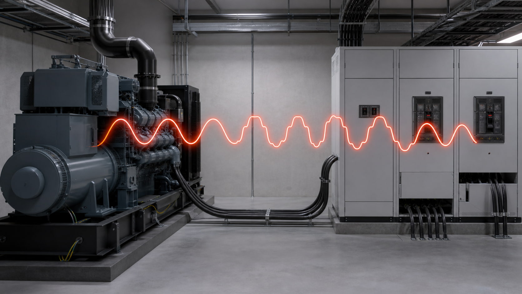
Una instalación puede funcionar con normalidad con la red eléctrica y desarrollar problemas de calidad de energía tras conectarla a un generador de reserva. Los variadores de frecuencia se desconectan, los sistemas UPS informan de fallos de entrada y las luces parpadean, aunque la carga no haya cambiado.
Las cargas no lineales suelen generar ya corriente armónica. El generador proporciona una fuente más débil, lo que permite que la misma distorsión de corriente genere una mayor distorsión de voltaje.
Los armónicos son componentes de voltaje o corriente que son múltiplos de la frecuencia fundamental. En un sistema de 50 Hz, el quinto armónico es de 250 Hz.
Las cargas no lineales consumen corriente en pulsos en lugar de seguir la forma de onda de voltaje de manera continua. Las cargas que suelen generar armónicos incluyen:
Variadores de frecuencia
Sistemas UPS
cargadores de baterías
Rectificadores
Iluminación LED
Fuentes de alimentación para ordenadores y servidores
Equipos de soldadura
Estas cargas generan corriente armónica tanto en la red eléctrica como en la fuente de alimentación del generador. La diferencia radica en la respuesta de la fuente.
La distorsión de voltaje producida en un bus depende de la corriente armónica y de la impedancia de la fuente:
Voltaje armónico ≈ Corriente armónica × Impedancia del sistema
La red eléctrica normalmente tiene una alta capacidad de cortocircuito y una impedancia relativamente baja. Un generador de reserva tiene una capacidad de falla mucho menor y una reactancia interna mayor. Cuando una corriente armónica fluye a través de esta impedancia más alta, la tensión armónica resultante es mayor.
La tensión distorsionada llega a todas las cargas conectadas, por lo que los equipos que funcionaban correctamente con la red eléctrica pueden presentar fallos de funcionamiento tras la transferencia.
| Condiciones de funcionamiento | suministro de servicios públicos | Suministro del generador |
|---|---|---|
| impedancia de la fuente | Generalmente bajo | Comparativamente alto |
| Capacidad de cortocircuito | Alto | Limitado |
| Respuesta a la corriente armónica | Menor distorsión de voltaje | Mayor distorsión de voltaje |
| Sensibilidad a los pasos de carga | Más bajo | Más alto |
| Condiciones de resonancia | Basado en la impedancia de la red | Cambio cuando el generador está conectado |
El dimensionamiento tradicional de generadores se centra en la potencia activa, la potencia aparente y el arranque del motor. Estos valores no describen completamente una carga no lineal.
Un sistema de alimentación ininterrumpida (UPS) o un variador de seis pulsos puede consumir corriente con un factor de cresta elevado y armónicos de quinto y séptimo orden dominantes. El alternador debe soportar estos componentes sin una deformación de voltaje excesiva.
Por lo tanto, al seleccionar un generador se debe considerar el porcentaje de carga no lineal, la distorsión armónica total de la corriente, los escalones de carga y la reactancia del alternador, y no solo la potencia aparente total (kVA).
Un generador de reserva puede alimentar un alto porcentaje de variadores de frecuencia, sistemas UPS y rectificadores, con poca carga lineal que diluya su efecto.
Los rectificadores de seis pulsos suelen producir armónicos de quinto y séptimo orden. Las cargas electrónicas monofásicas pueden generar armónicos de tercer orden que se suman al conductor neutro.
Entre los posibles resultados se incluyen una alta distorsión armónica total (THD) de voltaje, sobrecalentamiento del neutro y disparos intempestivos.
Con cargas ligeras, puede haber menor amortiguación del sistema, mientras que los equipos no lineales representan un gran porcentaje de la demanda total.
Por lo tanto, un SAI pequeño puede dominar la forma de onda del bus incluso cuando parezca insignificante en comparación con la potencia nominal del generador.
Pruebe varios puntos de funcionamiento; la carga máxima puede no producir la peor distorsión.
Los condensadores de corrección del factor de potencia interactúan con la inductancia de la fuente. Cuando la impedancia de la fuente cambia en el modo generador, la frecuencia de resonancia del sistema también cambia.
Un condensador que funciona de forma segura con la alimentación de la red eléctrica puede generar resonancia con la alimentación del generador, amplificando la distorsión o quemando los fusibles.
Revise el banco específicamente para el modo generador. Es posible que algunas etapas deban bloquearse, desintonizarse o reemplazarse con compensación dinámica.
Los ascensores, las soldadoras, los motores y las cargas cíclicas de los sistemas UPS pueden producir cambios rápidos en la demanda activa y reactiva.
El regulador de voltaje mantiene el voltaje en los terminales, pero no puede hacer que el generador se comporte como una fuente de alimentación eléctrica potente. Los armónicos y los cambios bruscos de carga pueden combinarse para producir fluctuaciones y distorsiones de voltaje.
Las capturas de formas de onda y las tendencias temporales ayudan a separar los armónicos de los problemas de regulación de voltaje y secuenciación.
| Síntoma durante el funcionamiento del generador | Causa probable | Qué medir |
| Alarma de entrada del SAI o transferencia a la batería | Distorsión armónica total (THD) de alto voltaje o variación de frecuencia | THDv, frecuencia y forma de onda |
| Sobretensión o fallo de entrada en el variador de frecuencia | Tensión distorsionada o transitorio de conmutación | Forma de onda de voltaje y corriente de excitación |
| Los fusibles del condensador fallan | Resonancia armónica o sobrecorriente del condensador | Corriente del condensador y espectro armónico |
| El conductor neutro se sobrecalienta | Corriente armónica de tercer orden o desequilibrio | Corriente RMS neutra y órdenes armónicos |
| Las luces parpadean cuando el equipo se enciende y apaga. | Cambios rápidos de carga y variación de voltaje | Tendencia de voltaje y corriente de paso de carga |
| El generador suena inusualmente ruidoso. | Par armónico, vibración o tensión magnética | Distorsión armónica total actual y armónicos individuales |
Utilice el mismo analizador y punto de medición en ambos modos de funcionamiento y, a continuación, compare los resultados de la red eléctrica y del generador.
Registro:
Distorsión armónica total (THD) de voltaje y corriente por fase
Individual harmonic orders
kW, kVAr, kVA and power factor
Phase and neutral currents
Frequency and voltage variation
Generator loading percentage
Capacitor-stage status
Waveforms during major load changes
Include transfer, load pickup, steady operation and the largest expected load step. Additional measurements may be needed at major nonlinear feeders.
The correct solution depends on the distortion source and operating conditions.
| System condition | Possible solution |
| Generator impedance is too high | Select a larger or lower-reactance alternator |
| One drive creates most of the distortion | Install a line reactor, DC choke or dedicated filter |
| Many changing nonlinear loads share one bus | Apply an Active Harmonic Filter |
| Capacitors create resonance risk | Use a properly engineered detuned bank or change generator-mode logic |
| Large loads connect simultaneously | Sequence load pickup after transfer |
| True power factor remains low | Separate harmonic distortion from reactive power demand |
| Sensitive equipment shares a distorted bus | Separate feeders or provide suitable power conditioning |
An Active Harmonic Filter must be sized from measured harmonic current and verified across the generator’s voltage and frequency range. Its current transformers must measure the intended compensation point.
A generator can have inherent distortion, but nonlinear loads are often the main harmonic-current source. Higher generator impedance converts that current into greater voltage distortion.
The acceptable level depends on applicable requirements and equipment sensitivity. Review individual harmonic orders as well as total voltage THD.
A larger generator may reduce voltage distortion, but alternator reactance, loading and the harmonic spectrum also matter. Size alone is not a guarantee.
Yes, but generator-mode resonance must be checked. Excessive capacitance may also cause leading power factor or voltage-control problems.
Install it near a dominant nonlinear load or at a common bus. The correct location depends on which part of the system requires harmonic-current reduction.
Harmonic distortion often increases on backup power because a generator is electrically weaker than the utility network.
El diagnóstico debe tener en cuenta la impedancia de la fuente, el porcentaje de carga no lineal, la corriente armónica, la interacción del condensador y los cambios de carga, no solo la potencia en kW y kVA del generador.
La solución puede incluir la selección del generador, la secuenciación de carga, la compensación de la desintonización, la mitigación en el lado del variador o un filtro activo de armónicos. Abordar la calidad de la energía durante el diseño es más fiable que solucionar problemas después de la puesta en marcha.



 compatible con la red ipv6