

 español
 English
 français
 Deutsch
 العربية
 中文
中文
Compensación de potencia reactiva SVG para
Estabilidad de la red eléctrica renovable
Una planta fotovoltaica puede perder bloques de inversores incluso cuando la irradiancia es estable. El desencadenante inmediato suele ser una variación de la tensión en el punto de acoplamiento común (PCC) tras el movimiento de las nubes, la conmutación de alimentadores o un cambio en la carga de un motor cercano. La compensación de potencia reactiva de SVG resuelve este problema de ingeniería inyectando o absorbiendo corriente reactiva con la suficiente rapidez para mantener el PCC, en lugar de esperar a la conmutación escalonada de los condensadores.
La generación renovable modifica la corriente de alimentación mientras interactúan los controles del inversor, la capacitancia del cable, la impedancia del transformador y una fuente de alimentación débil aguas arriba. Un proyecto que solo verifica la potencia nominal en MW puede pasar por alto la envolvente de corriente reactiva con una resistencia mínima de la red, lo que resulta en un factor de potencia deficiente, limitaciones en la exportación, activación de protecciones o fluctuaciones de voltaje.
Este artículo aborda los sistemas de recolección de baja y media tensión donde unSVGoSTATCOMSuministra vars controlables. Las normas IEEE 519 e IEC 61000 proporcionan el contexto para la planificación de armónicos, pero el acuerdo de interconexión define los criterios de aceptación del PCC.
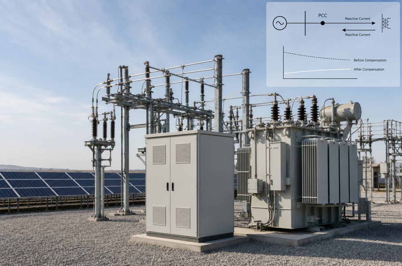
Armario YT ELECTRIC SVG conectado junto al transformador elevador en una subestación.
Un inversor puede regular la potencia reactiva, pero su límite de corriente es compartido por los componentes activos y reactivos. Cuando la producción solar se acerca al máximo, es posible que el inversor tenga poca capacidad de corriente disponible para el soporte de voltaje, a menos que la planta se haya sobredimensionado o limitado deliberadamente. Un inversor de fuente de alimentación externo separa parte de la carga dinámica de potencia reactiva del inversor de generación y preserva una mayor capacidad de potencia activa durante un evento de voltaje.
La primera relación física es sencilla: la variación de voltaje a través de la impedancia de una red sigue a la variación de corriente que la atraviesa. En un alimentador con reactancia significativa, los cambios de corriente reactiva alteran rápidamente el voltaje local. Un generador de circuitos integrados (SVG) mide continuamente el voltaje y la corriente, calcula el componente reactivo necesario y ordena a su convertidor que genere corriente capacitiva o inductiva mediante una estrategia de control de lazo cerrado.
A diferencia de un banco de condensadores, un SVG no espera un paso mecánico ni inyecta un valor fijo de kvar que varía con el cuadrado del voltaje. Puede absorber vars cuando la capacitancia del cable o los transformadores con poca carga elevan el voltaje, lo cual es importante cuando cambian las condiciones de exportación.
La interacción de control también es importante. Modele el nivel de cortocircuito del PCC, el grupo vectorial del transformador, las variables de carga del cable, los modos del inversor, las ramas pasivas y las etapas de condensadores existentes antes de asignar la capacidad del SVG.
Un SVG es un dispositivo de potencia reactiva dinámica, no un reemplazo automático para un filtro armónico activo. Antes de especificar un SVG, un AHF, un filtro pasivo o condensadores desintonizados, determine por separado el factor de potencia de desplazamiento, el factor de potencia de distorsión, la distorsión armónica total de voltaje y la THDi de corriente.
|
Criterio de ingeniería |
Banco de condensadores conmutados |
Compensación de potencia reactiva SVG |
|
Dirección de la corriente reactiva |
Inyección principalmente capacitiva |
Inyección capacitiva y absorción inductiva |
|
Comportamiento de control |
Pasos de kvar discretos y retardos de conmutación |
Corriente continuamente variable dentro de la capacidad nominal |
|
Dependencia del voltaje |
La salida varía sustancialmente con la tensión del bus. |
La salida controlada por corriente sigue la referencia del controlador. |
|
respuesta de rejilla débil |
Puede corregir en exceso o producir transitorios de conmutación. |
Puede realizar un seguimiento de los comandos rápidos de voltaje y factor de potencia. |
|
Interacción armónica |
Requiere evaluación de resonancia y desintonización. |
Requiere una evaluación de compatibilidad armónica; no sustituye al AHF cuando se necesita la cancelación de corriente armónica. |
|
Tipo de energía renovable típico |
kvar base estable en alimentadores predecibles |
Soporte de voltaje PCC rápido, variadores de potencia de cable variables y generación fluctuante |
La especificación de la hoja de datos no garantiza la corriente nominal en las condiciones de instalación. Es necesario especificar la temperatura ambiente, el flujo de aire, la altitud, el rango de voltaje, el estado de la carcasa y el ciclo de trabajo; a 45 °C de temperatura ambiente, la temperatura de la unión del semiconductor y la resistencia del disipador de calor pueden requerir una reducción de la capacidad nominal.
Una topología de tres niveles reduce el salto de voltaje que experimentan el reactor y los dispositivos en comparación con una configuración de dos niveles similar. Un menor dv/dt y una tensión de voltaje distribuida en los dispositivos pueden reducir el estrés térmico cuando la frecuencia de conmutación, el diseño de refrigeración y la clase de voltaje coinciden adecuadamente.
La modulación SPWM convierte una referencia de corriente en comandos de conmutación; su calidad afecta al error de seguimiento, la ondulación, la demanda del reactor y las pérdidas de conmutación. La selección de IGBT y MOSFET de SiC debe tener en cuenta la clase de tensión, la frecuencia de conmutación, el diseño térmico, la facilidad de mantenimiento y el coste del ciclo de vida.
Defina los límites de tensión anormal, la prioridad de corriente, la coordinación de tolerancia a fallos y la rampa de recuperación. Coordine el control del SVG con la protección del inversor, la protección diferencial del transformador, los relés del alimentador y los ajustes de la red eléctrica para evitar disparos inducidos por el control.
|
Estado del sitio |
Mediciones y datos de entrada del estudio |
Lógica de selección preliminar |
Nota de configuración |
|
Planta solar conectada a una red eléctrica robusta con exportación estable |
Tendencia del factor de potencia del PCC, potencia reactiva de carga del cable, carga del transformador |
Tamaño para la demanda reactiva diaria residual más el margen de control requerido |
Utilice condensadores fijos solo después de evaluar la resonancia; SVG se encarga del ajuste fino. |
|
PCC solar o eólico para redes débiles |
Nivel de cortocircuito, pruebas de escalón de voltaje, margen de corriente del inversor |
Capacidad base en función de la demanda de corriente reactiva en el peor de los casos durante escenarios de exportación y perturbaciones. |
Verifique la prioridad de respuesta y la interfaz de comandos del código de cuadrícula. |
|
Long MV collector network |
Cable capacitance, voltage profile, light-load overvoltage |
Include inductive absorption capacity, not only capacitive kvar |
Place measurement and control reference at the contractual PCC where required |
|
Hybrid plant with BESS |
Charge/discharge modes, transformer impedance, control hierarchy |
Model simultaneous inverter and SVG var commands before rating |
Define a single supervisory voltage/PF controller to prevent hunting |
|
Hot, dusty industrial renewable site |
Maximum ambient, derating curve, IP enclosure, maintenance access |
Confirm rated current at the specified ambient or select a larger frame |
Specify filtered airflow, heat rejection, and planned inspection access |
Consider a representative Middle East industrial park with a 33 kV utility connection, rooftop solar, and 0.4 kV/11 kV loads through multiple transformers. VFD-driven pumps and compressors make renewable export coincide with dynamic industrial demand; this is a design case, not a named customer record.
During feeder transfers, generator and inverter protection becomes sensitive: PCC voltage changes rapidly, the capacitor bank switches in steps, and power factor leaves its target. Record synchronized voltage, current, THDi, power factor, capacitor state, solar output, and generator status to separate VFD ramps from capacitor-switching effects.
Select a 33 kV STATCOM or transformer-coupled SVG from the modeled reactive-current envelope, revise capacitor logic, and complete harmonic checks. Use a PCC voltage or power-factor reference with current limiting and coordinate inverter and SVG commands; apply a separate AHF or passive-filter study if measurements identify material harmonic current.
Define acceptance before commissioning: stable PCC voltage across agreed transitions, utility-compliant power factor, no control hunting, and THDi evaluated at the agreed measurement point. Verify with a calibrated power-quality analyzer and event captures, without inventing a percentage improvement or return-on-investment claim.
Start with time-series measurements or a validated load-flow and dynamic model, not plant MW alone. Calculate worst capacitive and inductive current at the PCC across export, low generation, switching, BESS modes, and minimum short-circuit strength; then confirm rated current at site ambient and voltage.
It depends on the connection point, isolation, protection changes, and utility permits. Final cable termination, CT/PT work, and protection commissioning usually require a controlled outage or approved live-work procedure.
No. El SVG proporciona compensación reactiva dinámica; un filtro armónico activo se centra en los componentes de corriente armónica y puede proporcionar compensación de corriente neutra cuando esté diseñado. Verifique la resonancia del condensador, la secuencia de conmutación y la interacción del SVG antes de la operación en paralelo.
Inspeccione los circuitos de refrigeración, los ventiladores, los filtros, las conexiones del reactor, el par de apriete de las barras colectoras, el aislamiento y las alarmas. En instalaciones con altas temperaturas o polvo, verifique la capacidad nominal de la carcasa, la reducción de capacidad, el circuito de aire y las piezas de repuesto según el manual del equipo y las especificaciones de funcionamiento de la instalación.
La compensación de potencia reactiva SVG proporciona a los proyectos de energía renovable una fuente controlable de corriente reactiva dinámica cuando el margen del inversor, los condensadores conmutados y la impedancia de la red no pueden mantener estable el PCC por sí solos. La especificación correcta comienza con transiciones operativas medidas o modeladas, separación de armónicos, carga térmica, coordinación de control y puntos de aceptación del código de red. Comuníquese con la División de Calidad de Energía de YT Electric para una revisión específica del proyecto de diagramas unifilares, mediciones de PQ, condiciones ambientales y la filosofía de control SVG o STATCOM requerida.
Explore las especificaciones de los productos y la guía de aplicación de YT Electric:https://www.ytelect.com/blog/guide-to-selecting-active-harmonic-filters_b321
Referencia: IEEE 519-2022, Norma IEEE para el control de armónicos en sistemas de energía eléctrica:https://standards.ieee.org/ieee/519/10677/
IEC 61000, Compatibilidad electromagnética (CEM): IEC 61000-4-30:2025 | IEC



 compatible con la red ipv6